Einleitung

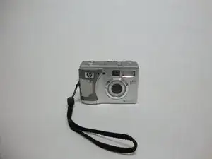
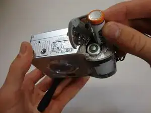
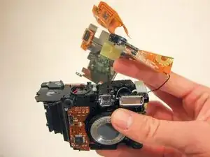
This guide is meant to teach the reader to install a new viewfinder mirror and lens. If the lens or mirror are no longer working or broken, this guide will help the reader replace them with new ones.

  1. pcUmacIwYDEKaeKJ
    pcUmacIwYDEKaeKJ
    vhLIWCAVkl1jaFww
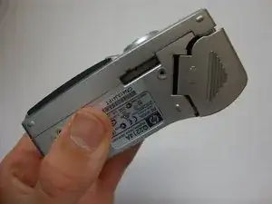
    • Flip the camera over so the bottom is facing you.

  2. EqOxGSDrkZKj1VRR
    EqOxGSDrkZKj1VRR
    TNSOidZtgfwg3wTM
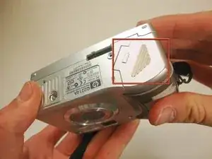
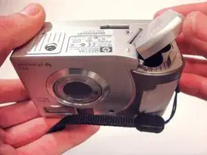
    • Slide the bottom cover in the direction of the arrow to open it.

  3. M3nae2bVbub2r5CO
    • Pull out the batteries.

  4. 4l3B1wiQVUUnt24e
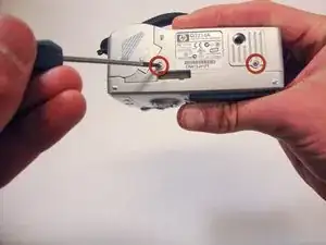
    • Using a Phillips #00 screwdriver, remove the two 4.70mm screws in the bottom of the plastic casing.

  5. EtUv1xytV3EHFDW6
    EtUv1xytV3EHFDW6
    1rAiJRqw4DpUgHCR
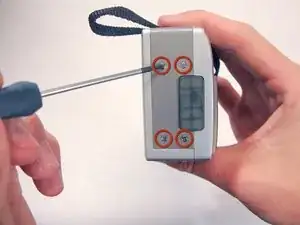
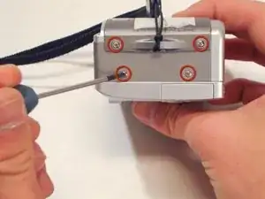
    • Remove the four 4.70mm screws on the left side of the camera.

  6. BW1nqe1eK3BEhBg1
    BW1nqe1eK3BEhBg1
    CPFkySUkhsRYZmfU
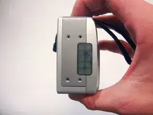
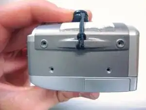
    • Remove the four 4.70mm screws on the opposite side of the camera.

  7. GFCuVopd1cukUFvO
    GFCuVopd1cukUFvO
    WGVFniuVGCD4pX2a
    W4QkWtLS6Pchm1ER
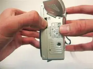
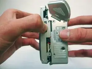
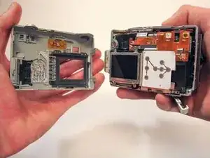
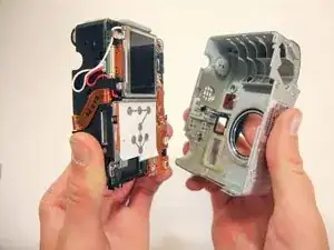
    • Use your thumbs to pry the case apart.

    • It is easiest to pry the case apart if you start at the bottom.

    • The case should come apart with minimal effort. If it doesn't, you can use a spudger or plastic opening tool to pry it open.

  8. 5ShJH21JHb2n2aSa
    • This step requires a significant amount of force.

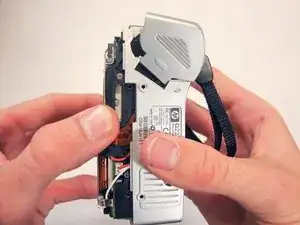
    • Pull the bottom half of the inner camera out of the case by half an inch. This may be difficult and require some force.

  9. TQQlM5ipUoRaOBUZ
    TQQlM5ipUoRaOBUZ
    JYiNvCPXvMwlgAGi
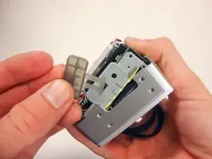
    • While pulling the camera out of the case, note the small soft plastic cover on the side. This cover will detach from the rest of the device.

    • Once the bottom of the inner camera is pulled out, pull the device out completely.

    • Use a firm grasp when removing the device from the case for stability and control.

  10. pORbmX6kK2IZjyBq
    • Orient the camera so that the LCD screen is facing you.

    • If case is still on, remove it by following the Plastic Casing Installation Guide found in the previous steps.

    • Removing the casing completely is crucial to completing this guide.

  11. RCSvGUjKrY5y3BAl
    RCSvGUjKrY5y3BAl
    1ZJ31fiYVMntVQnc
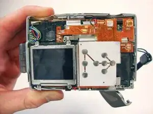
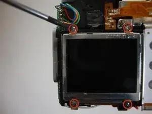
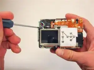
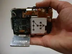
    • Using a Phillips #00 remove the four 4.40 mm screws that secure the LCD screen to the frame.

  12. 3KtAQYbkgwW1G2nm
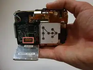
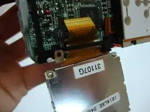
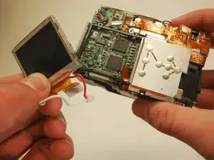
    • Allow the LCD screen to flip down. This will expose the electric strip that connects the screen to the camera.

  13. JQepbYBwNTW2e4uQ
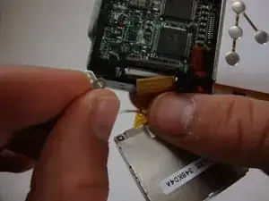
    • Look for where the yellow electric strip is attached to the camera. You will find a plastic grey bar and a white base holding this strip in place.

    • Push the grey bar away from the white base. This will release the yellow electric strip and free the LCD screen from the camera.

  14. MvPTgBQ2hVQOAZG3
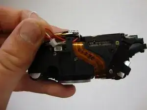
    • Unplug the connected red and white wires. They will come out with the small white casing.

  15. Clr3McPRhLeEErpi
    • Flip camera so that the lens is facing away from you. You should be looking at the LCD screen.

  16. hlAePlpNAntse365
    hlAePlpNAntse365
    Kds6lXNOZTQGwViu
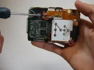
    • Remove the bottom left LCD mounting frame screw. The screen should come loose after the screw is removed.

    • Remove the LCD screen from the camera. Make sure that the electric strip comes out with screen.

  17. O2DLBp1sL1RLIpDR
    • Remove the two screws securing the electric strip casing on the back of the camera.

  18. SdKmVarEB16xRAEq
    • Flip the camera over so that the top is facing you. This is the side with the main button.

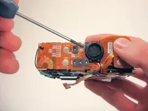
    • Remove screws securing the electric strip casing near the speaker

  19. S5rE55ApfEVP3AdM
    • Flip the camera over so that the back is facing you. This is the side where the LCD screen used to be.

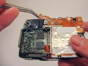
    • Pull the end of the electric strip off of the back of the camera with tweezers.

  20. cDeeeNXhtXqHe43C
    • Pull the electric strip off of the top of the camera with tweezers.

    • By now, you should have two ends of the electric strip detached from the camera.

  21. m3basgYS1XwKH2Fn
    • Using your fingers, fully detach the strip along with the casing. This should come off easily. Be careful not to rip or tear any of the electric strip.

    • The black wire should not be broken or removed. This will damage the camera.

  22. YPt1NFkpQQfPHlaC
    YPt1NFkpQQfPHlaC
    BtPs6Xm1YLlRQvZB
    • Orient the camera so that you are looking at the back of the camera. This is right above where the LCD screen used to be.

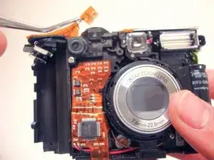
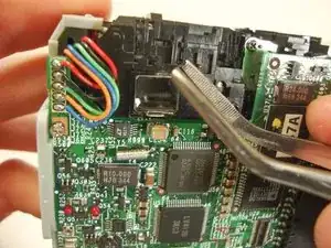
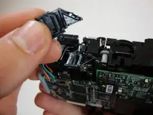
    • Detach the clip of the viewfinder cover with the tweezers.

    • Push up and remove the viewfinder cover.

  23. 224125AhX25OX6OQ
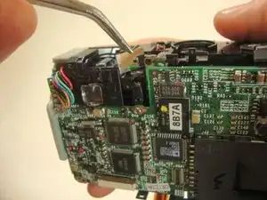
    • Remove the viewfinder mirror by pulling up on the mirror with tweezers.

Abschluss

To reassemble your device, follow these instructions in reverse order.

Nick Oleskowicz

Mitglied seit: 04/04/12

275 Reputation

0 Kommentare