Einleitung

  1. HVuTTqMgXqfDsOIV
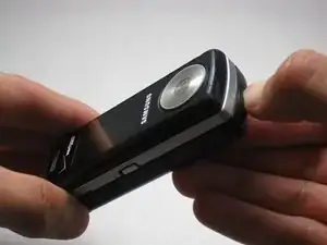
    • Locate the button on the bottom of the phone. Once located, press and hold the button down.

  2. n5WeUWogtm1nlYlS
    n5WeUWogtm1nlYlS
    CMYW1i1QoplUcEpL
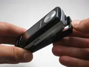
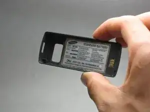
    • While holding the button down, remove the back cover of the phone.

  3. mNqEvshBEIqOCAlP
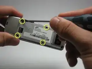
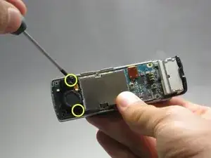
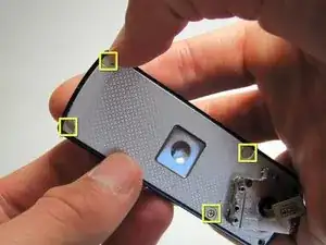
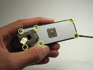
    • Use the size 00 Phillips screwdriver to remove the four screws located on the back of the phone. These screws are circled in yellow in the given image.

  4. SJnTcHkERUcXZDrE
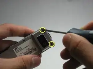
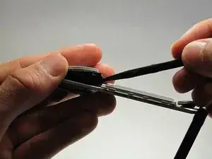
    • Using the same 00 Phillips screwdriver, remove the two screws at the bottom back plate of the phone near the camera and the speaker.

    • These screws will be 7.25 mm long.

  5. XY6Op3WCiUFCTNXa
    XY6Op3WCiUFCTNXa
    WNYVjZQf5dRFd2tf
    tdSkJFt5JiVHSTkN
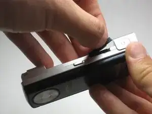
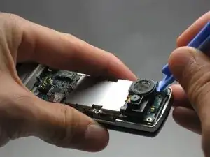
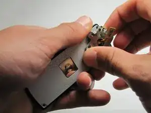
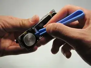
    • Before proceeding, locate the USB port (where the charger can be plugged in) and open it using the iFixit Opening Tool.

    • Failure to open USB port cover at this stage may result in damaging the device.

  6. OwIadncBGglETODd
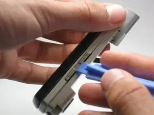
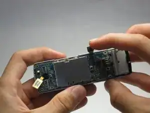
    • Remove the screws on either side of the camera/speaker with a Phillips 00 screwdriver.

    • These screws will be 5.45 mm long.

  7. UmqYUOltrbGeX4wo
    UmqYUOltrbGeX4wo
    JJ5CEWB65XKnkU6A
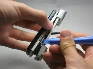
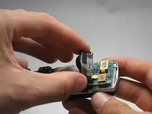
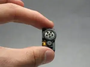
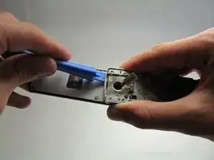
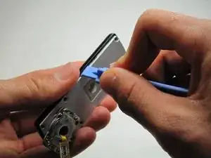
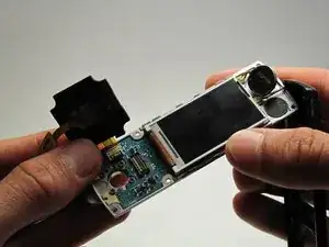
    • Use the iFixit Opening Tool to begin removing the camera/speaker from the logic board.

    • Practice caution to prevent damage to the attaching ribbon.

  8. JpZEsFUIeHyAPpdG
    JpZEsFUIeHyAPpdG
    MvUM5WpKkikTD4VZ
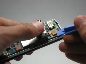
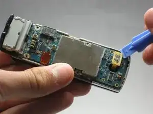
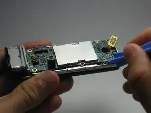
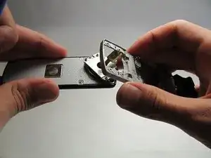
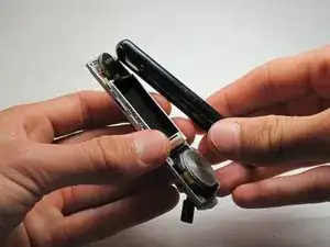
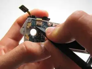
    • To completely remove the camera/speaker, locate the orange attachment beneath it (as shown in the image).

    • Then, use the iFixit Opening Tool to gently pry the camera/speaker off.

  9. 1GkYSsdrCrKyZOav
    1GkYSsdrCrKyZOav
    TefJjhfGmv2xrFOO
    • Use the iFixit Opening Tool to pop off the yellow tab on the logic board.

  10. isWytmtnj2bDR42i
    isWytmtnj2bDR42i
    3VHJbFU1G3gDsgPY
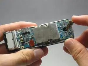
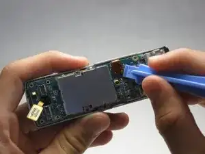
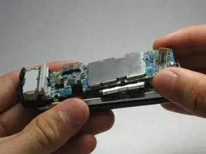
    • Use the iFixit Opening Tool to pop off the other orange tab to free the logic board.

  11. 52GmIpr12b3siNtR
    52GmIpr12b3siNtR
    QYYxI6Ro12MUQWOK
    VSXnpBveLyxX6YKL
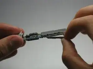
    • To completely remove the logic board, use the iFixit Opening Tool to pop it up, then use your fingers to pull it out.

    • Do not be alarmed if the volume and hold switch buttons are removed from the logic board.

  12. i21r6dDXrtwcf6OO
    i21r6dDXrtwcf6OO
    y1uaxqOCZSEHZYUJ
    KqhyXsEdMFMa3nak
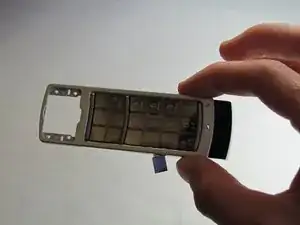
    • Open/swivel the phone so the back of the LCD panel is visible.

    • Use the iPod opening tool to pry the keypad from the hinge on the back of the device.

    • A moderate amount of force may need to be applied.

  13. bwhwhVGAt1fEriFp
    bwhwhVGAt1fEriFp
    EOJtXCyOWwGsNryP
    • Using your fingernail, remove the stickers covering the screws on the back of the LCD casing.

    • Using a phillips 00 screwdriver, remove all six screws on the back of the device.

    • These screws will be 3.45 mm long.

  14. dJNqHv2yyRcYj2sy
    dJNqHv2yyRcYj2sy
    bJmtJhgmnFbYsjIE
    faiphmXgva2YCpcM
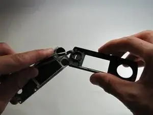
    • Using a generous amount of force, use your hands to pry loose the casing from the LCD panel.

    • If necessary, use the iPod opening tool to completely free the casing.

    • Be careful not to sever the wire connecting the outer casing to the display board.

  15. CoIqGKRvAUS5NFme
    CoIqGKRvAUS5NFme
    sWxQMBA3UHHlCWnw
    3jvtlZcKVyeY2x5a
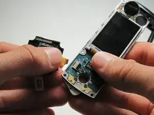
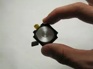
    • Using the iPod opening tool, remove the click wheel from the board.

    • After you have freed the edges, use the spudger to release the clip holding it flush to the board.

  16. ojZOaApAAMDGPuhc
    ojZOaApAAMDGPuhc
    LbKEhllndvlKMp5T
    XLQkBKKd6E3JcU5g
    • Unlock the ribbon connection by pressing down on the black clip.

    • Carefully pull the click wheel away from the device.

  17. 5LQsTWPHbVnaM3Gr
    5LQsTWPHbVnaM3Gr
    XZrQMWo3a3neSNoX
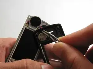
    • Using tweezers, grip the red and blue wires that attach the audio earpiece to the outer casing and pull.

    • This is glued on so a moderate amount of force may be needed.

Abschluss

To reassemble your device, follow these instructions in reverse order.

Ryan Turner

Mitglied seit: 16/04/10

99 Reputation

0 Kommentare