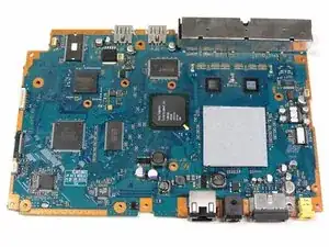
Einleitung
Werkzeuge


-
-
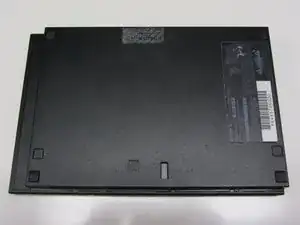
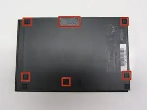
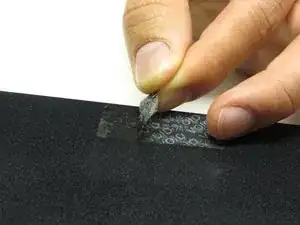
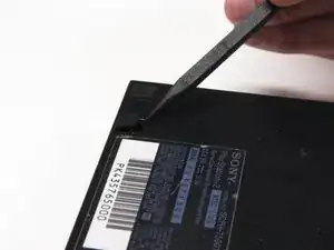
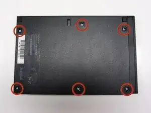
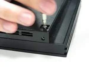
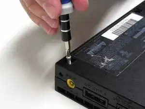
Locate the 6 feet on the base of the unit. Pry them off using a spudger to reveal the screws.
-
-
-
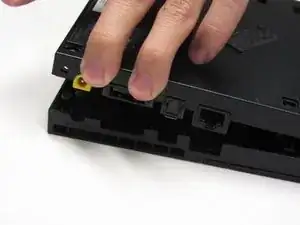
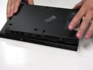
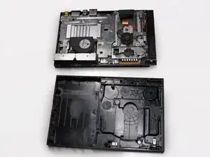
Starting at the corner at which the power and Ethernet ports are located, pry open the outer shell using a spudger and continue around the entire unit.
-
-
-
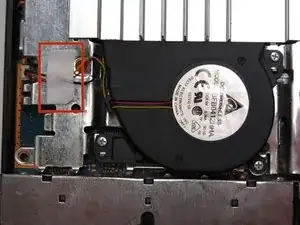
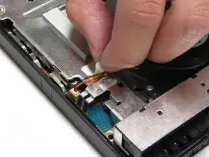
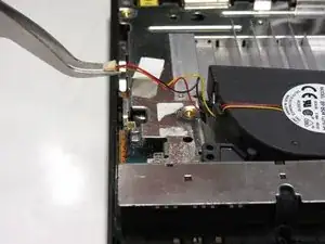
Lift the connector from the motherboard with a pair of tweezers using a firm, upward force.
-
-
-
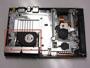
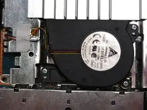
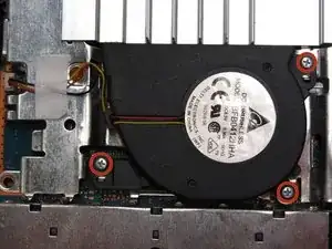
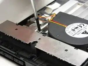
Remove all three 1.6 mm screws fastening the fan to the unit using a #1 Phillips screwdriver.
-
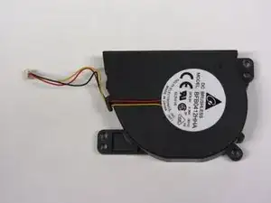
Gently lift and remove the fan from its compartment.
-
-
-
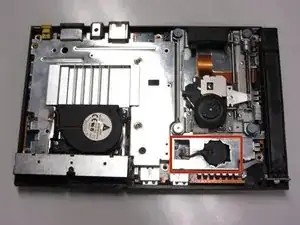
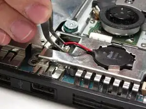
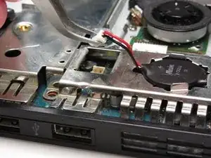
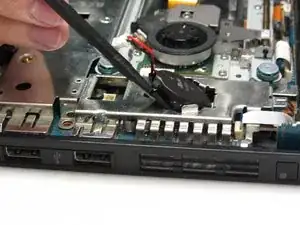
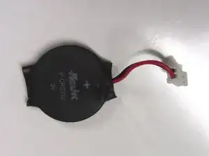
Locate the clock battery at the front, right section of the unit. The battery has a circular shape with red (+) and black (-) wires connecting to the motherboard.
-
-
-
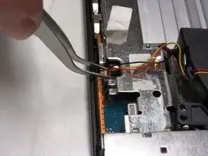
Lift the connector from the motherboard with a pair of tweezers using a firm, upward force.
-
-
-
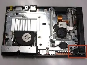
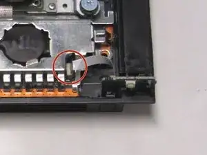
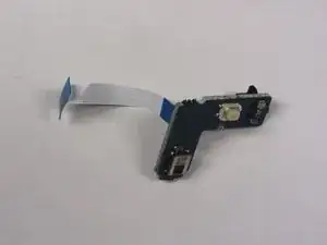
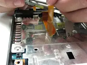
Gently detach the ribbon cable connecting the IR sensor to the motherboard.
-
Caution: Always remove ribbon cables by the plastic handles located on either end. Gripping a ribbon cable anywhere but the provided handles can damage the cable and render the component useless.
-
-
-
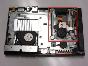
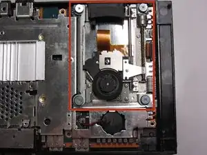
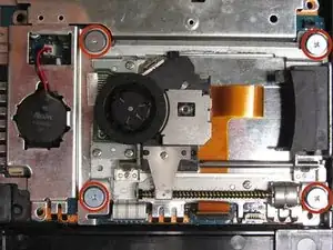
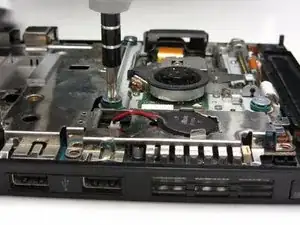
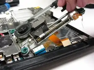
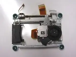
Locate the optical drive which occupies most of the space on the right side of the unit. It can be identified by the four screws with wide-diameter heads fastening the optical drive to the motherboard.
-
-
-
Remove any tape fastening the cables to the motherboard and gently lift and remove the optical drive.
-
-
-
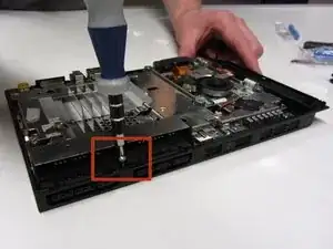
Remove the 2.4 mm screw located in between the controller ports using a #1 Phillips screwdriver.
-
-
-
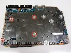
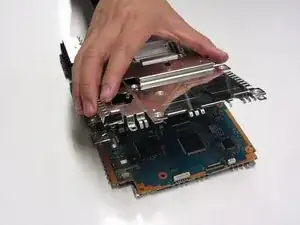
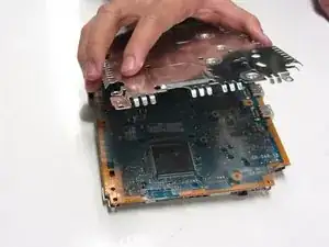
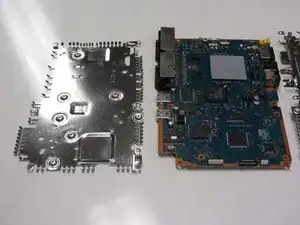
There are a total of five 1.6 mm screws which mount the metal chassis to the motherboard.
-
Remove the screw on top and the four screws on the bottom with a #1 Phillips screwdriver.
-
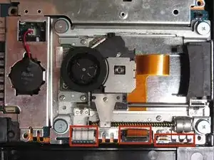
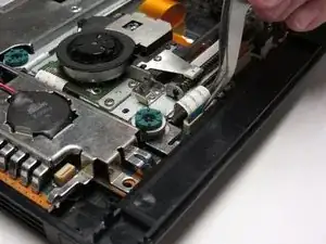
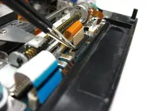
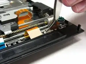
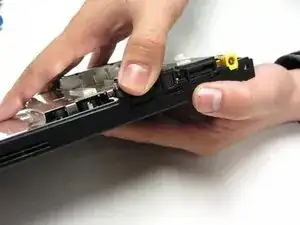
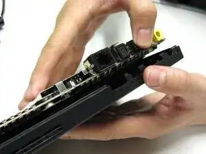

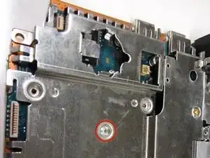
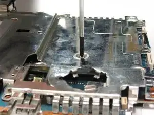
To reassemble your device, follow these instructions in reverse order.

4 Kommentare
نرجو اضافة اللغة العربية
you can choose the translate mode in google chrome and it will be automatically translated for you hill climb racing
HTML ve CSS notlarım için kişisel internet adresimi ziyaret edin - Cevdet Buğra Şahin