Einleitung

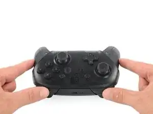
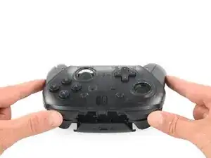
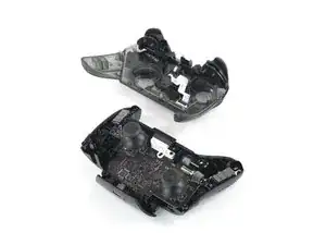
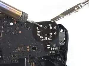
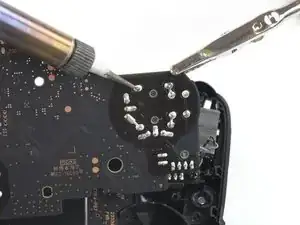
Diese Anleitung zeigt, wie du defekte Joysticks in deinem Nintendo Switch Pro Controller austauschen kannst. Du musst dazu Kenntnisse im Löten haben. Beim Abnehmen der Kunststoff-Gehäuseschalen und der Leiterplatten musst du besonders vorsichtig sein, damit das Gerät nicht unrettbar beschädigt wird. Bei dieser Reparatur wird auch der Lithium-Ionen-Akku ausgebaut, wenn dieser aufgebläht ist, musst du geeignete Vorsichtsmaßnahmen treffen.

  1. iaKRfcPV2HNC5yUK
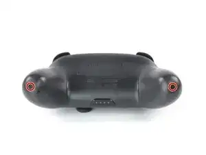
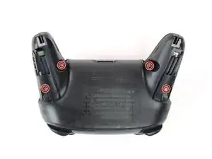
    • Drehe den Controller so um, dass der Aufkleber mit der Modellnummer nach oben zeigt.

    • Entferne die beiden schwarzen 8,4 mm Flachkopf-Kreuzschlitzschrauben, mit denen die Handgriffe am Ende verschraubt sind.

    Be carefull, these screws are super easy to strip even with the right tools.

    Lukas Eberharter -

  2. pFHHOlTyvlQ43DOC
    pFHHOlTyvlQ43DOC
    KCE54LsPyGnuWTkW
    UNYZtREEKVfHallZ
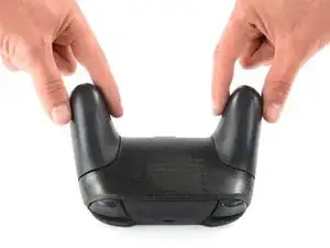
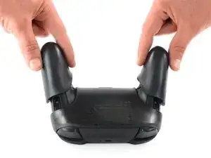
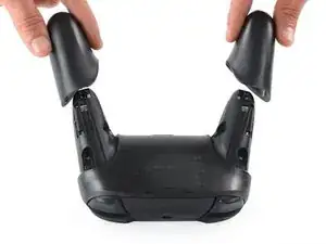
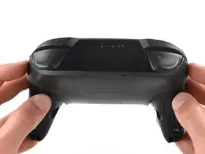
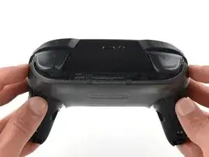
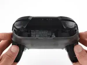
    • Ziehe die Abdeckungen der Griffe vorsichtig vom Controller.

  3. 3OnYDcOU1gVR2fEG
    • Entferne die vier silberfarbenen 6,8 mm Kreuzschlitzschrauben #00, mit denen die durchsichtige Abdeckung befestigt ist.

  4. Zb3Ool4Evh63KKVd
    Zb3Ool4Evh63KKVd
    E4qBEgOibCQbXlIJ
    jihxJQfDSqclVJnF
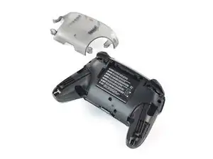
    • Löse die durchsichtige Abdeckung mit deinem Fingernagel ab.

  5. p4bHAkTpIvuBFIfc
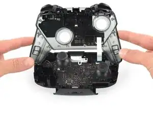
    • Entferne die durchsichtige Abdeckung.

  6. yUbMYllrTC6sSOGL
    yUbMYllrTC6sSOGL
    6pxWhyQpxoXGbs22
    vEF6WXIGCHUebiZO
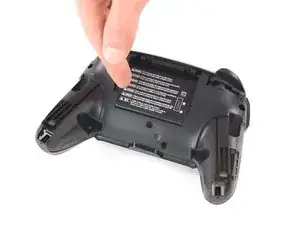
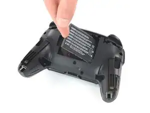
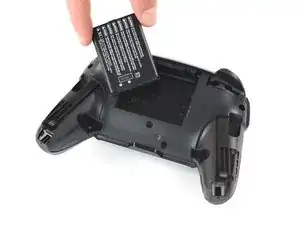
    • Entferne den Lithium-Ionen-Akku, indem du ihn mit deinem Fingernagel oder einem Öffnungswerkzeug an der linken Seite anhebst.

    • Dafür brauchst du nur wenig Kraft.

  7. 41hYi1SofYMKVF4B
    41hYi1SofYMKVF4B
    IhtOVVcrnx5IBHgJ
    WJ4LvGQlKLhlREns
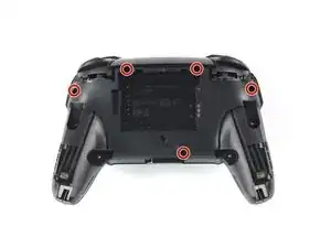
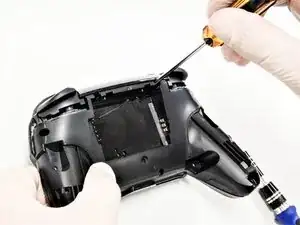
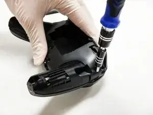
    • Entferne die fünf 6 mm Kreuzschlitzschrauben auf der Rückseite des Controllers.

    the 2 screws up at the top are unreachable with the standard fixit kit just a heads up

    Andrew Feliz -

    Seconded. the screws are located too deep below the plastic slot, and the bit holding bulge is too wide for the small aperture (similarly with the flexible extension). the bit length is too shallow to reach.

    An alternative driver with a much narrower & longer shaft is required, which will likely not come with interchangeable bits.

    Douglas Selby -

    I would say it is possible to reach the top left screw, just not the top right - there is a gap in the top left that allows you to slightly bend the standard driver outward to turn it while still making adequate contact.

    El_Mechacontext -

    An update: I was actually able to remove the top right one in a really hacky way - inserting the Phillips #0 bit into the #4 hex bit, and then using that in the standard driver. This added just enough length to successfully reach and make full contact with the screw!

    El_Mechacontext -

  8. PnIrdtdY4KCyxuKK
    PnIrdtdY4KCyxuKK
    ZBKtxPXnhQuBTaDN
    OZcevYGCPPARFaRx
    • Nimm die Kunststoffabdeckung des Controllers behutsam ab.

    • Entferne die Abdeckung noch nicht ganz, sie ist noch mit einem weißen Flachbandkabel an der Hauptplatine angeschlossen.

    Didn't realize there is adhesive holding the front cover onto the unit. It's located inside of the handles. Just a bit of force there helped, just be careful of the cable.

    Roger Perez -

  9. NpVhXDsYSWmW4tBT
    NpVhXDsYSWmW4tBT
    QXe1DlCMuCXbrveX
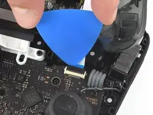
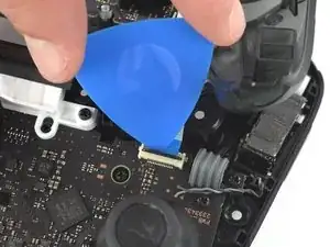
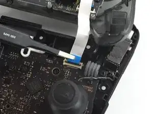
    • Drücke den schwarzen Sicherungsbügel am ZIF-Anschluss mit der Spitze eines Plektrums zum Öffnen nach oben.

  10. 3qj6VtFJtKAHHm6I
    3qj6VtFJtKAHHm6I
    YJvaLXngDhvHF1Gr
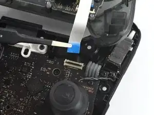
    • Löse das Verbindungskabel mit deinen Fingern oder einer stumpfen Pinzette aus seinem Anschluss.

  11. OpC2vBHXBB35uAQ4
    • Entferne das vordere Gehäuseteil.

  12. fmhalkYPurcsCRYL
    fmhalkYPurcsCRYL
    elaYKLLtkDSyGABw
    rEIOPXEXhFo3sEO1
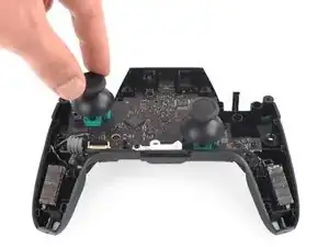
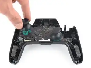
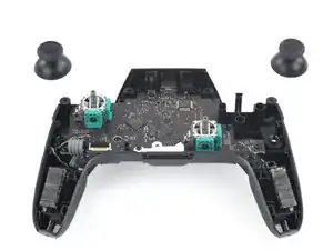
    • Ziehe mit leichter Kraft die beiden Joystickkappen vom Controller ab.

  13. dTuT4xSHUxiNECZU
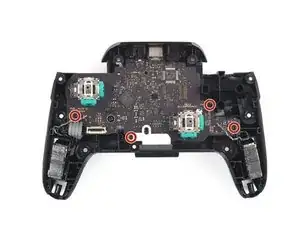
    • Entferne die vier 5 mm Kreuzschlitzschrauben, mit denen die Hauptplatine befestigt ist.

  14. BMiSYbhVXs6Z3Y6U
    BMiSYbhVXs6Z3Y6U
    sZdbNwAjKaEEAa2e
    SM4NBN5cFyWiAWXF
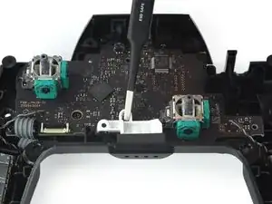
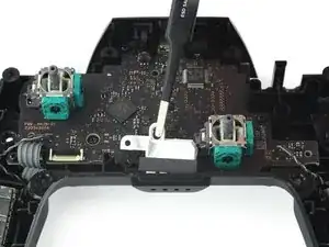
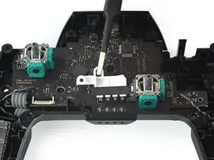
    • Löse das LED-Licht mit mit einer Pinzette oder deinen Fingernägeln aus seiner Fassung.

    • Lege das LED-Licht samt seiner Schraube bis zum Zusammenbau zur Seite.

    You are not removing the 4 LEDs here, they are soldered on the board. You are only removing the light transporting plastic piece.

    Uncle BenZ -

  15. ZhSJFHfoB5uIhdwh
    ZhSJFHfoB5uIhdwh
    FocRPjIyriVEQ5Y6
    BgjPKaESfuRXL5Bj
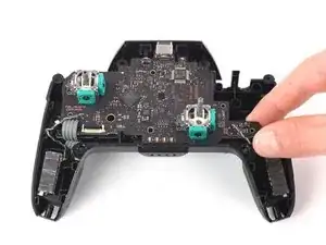
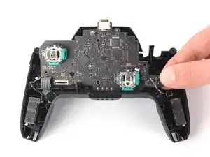
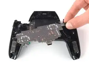
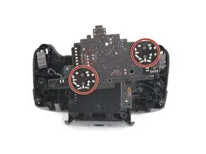
    • Löse die Platine aus dem Gehäuse, indem du sanft an der unteren rechten Ecke ziehst.

    • Hebe die Platine hoch, um an die Rückseite zu gelangen.

    • Setze hier nicht zu viel Kraft ein, du könntest die Kabel beschädigen.

  16. uia1EpJV3nO4epIX
    uia1EpJV3nO4epIX
    UGJsFktqRYicBsPH

    Bonjour,pour dessouder les joysticks, qu’avez-vous utilisez comme outil: de la tresse ou une pompe à dessouder ?

    Par avance merci.

    Patrick

    le hellegouarch -

    J’ai utilisé une pompe, avec de bons résultats

    Brian -

Abschluss

Um dein Gerät wieder zusammenzubauen, folge den Schritten dieser Anleitung in umgekehrter Reihenfolge.

Daniel Tagalog

Mitglied seit: 10/10/19

1048 Reputation

13 Kommentare

I managed to replace mine with much difficulty with the soldering but the stick does not seem to turn fully anymore, both with the replacement and the original. For reference, when I go to test it, it no longer registers as reaching the outer circle when pressed all the way down. Similarly when I go to calibrate it, it only reaches up til about the 2nd outer circle, not enough to actually trigger the green arrow. Since this seems to occur on both the replacement and original stick now, I’m guessing this must be some issue that arose while I was struggling with the desoldering process. Anybody have any ideas what might be causing my issue? Have I just damaged it beyond repair?

Tyler -

Without pictures it is impossible to tell, but there is the possibility that you strips the metal connection on the solder point. This is fixable by “bridging” the connection. You will want to find schematics of the wiring for the PCB and then solder the wire over to the next connection.

As a side note, I should mention that I have never tried this on a controller of any sort and that I have only used this method on keyboards with single wire connections. It is possible that the connection in a controller PCB have more going on and that this technique will not work.

Gavin A -

I have the same problem, I buy 2 joystick module from iFixit and the two gave me the same issue, the joystick module don't reach the green arrow.

I can't calibrate because of that issue.

Any ideas?

Piero Grasso -

I have also had the same issue with replacement, only reaches roughly 75%. I contacted ifixit and they sent me a replacement thinking it might be a faulty pot, I installed the new stick and have the same issue. Maybe different years used different resistance.

marcos aguilera -

Excellent guide. Thank you. Saved me from having to buy a $70 controller.

One comment though, all the screws are actually Phillips #0 except for the grip screws, which are Phillips #00

Brian -

I managed to repair a drifting stick input without any soldering by just replacing the potentiometer in the stick module. You can pry open the housing on the sides, swap it out (make sure it’s the right orientation), and snap it back into place. Potentiometers for Dualshock 4 analog sticks worked for me—apparently these parts are industry standard. Doing this from now on for all my drifty sticks.

Scott Baker -

Hi Scott —

.

So, first off, thanks for the tip! Now, I realize I may be asking a bit much of you here, but, is there any chance you could post/take/fwd any pics of the (sub)procedure you describe? It’d be really helpful to have a reference like that before I tear into a functioning joystick — even if it has a sporadic (though no less infuriating for that) issue.

.

If that’s not feasible, then perhaps you know of and can post a link to a decent guide for doing so on any of the platforms that use these (apparently standard) items?

.

Thanks in advance for any help on this! :oD

anatinus -

I would like to try it your way. Do you have any pictures or something like it. Maybe a video?
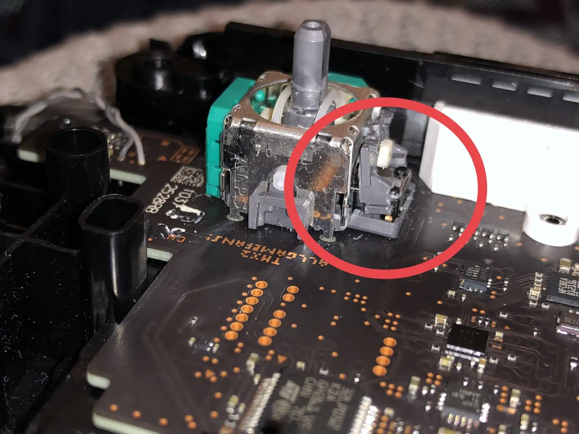
André Schenkels -

Do you know how to correctly reassemble the grey piece in the picture?

First thought was something had snapped but after popping off the same piece from the other (working) thumbstick they seem to be identical and neither the part nor the socket seems damaged. I also can’t see any evidence of glue.

The problem is I can’t get the part to clip back into place - it is supposed to sit flush and taught without any movement when the stick is rotated. But no matter how I reapply it I can’t clip it into place.

https://i.imgur.com/mFOQEUy.jpg

Casey -

After doing this. I lost charging capabilities and the capability to even plug it into a PC. Any advice will be beneficial.

Jose Godoi -

I think the grip screws are JIS #00 which would make sense since this is made in Japan.

jorach -

After replacing my analog with one from iFixIt I am only getting about half range on my analog and cannot complete recalibration. I tried 2 analogs from iFixIt with the same issue. I replaced with the original and have full range again

Peter Roach -

I destroyed some of the wiring, but measured connections on the other stick, and used a thin wire to re-wire the broken connection from top to bottom. Works great, even could calibrate it without issues. Unfortunately I broke the thick wires soldering that connects the battery, I’ll need some more delicate equipment to fix that one, until then it works fine when connected to power with cable.

Thraex Aquator -