Einleitung

Die Kontakte an diesem 72 Pin Anschluss können sich verbiegen und die Cartridge kann nicht mehr gelesen. Dann muss er ausgetauscht werden, dies wird hier beschrieben.

  1. aWptGiRVTeq1GLPj
    aWptGiRVTeq1GLPj
    X2DlKA2PHkWZSJno
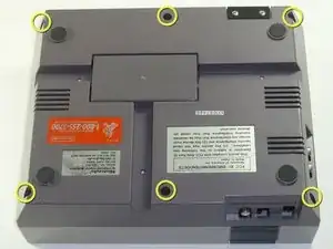
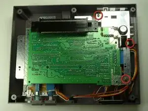
    • Entferne die sechs 13,25 mm Kreuzschlitzschrauben an der Bodenplatte der Konsole.

    • Die Schrauben sitzen 40 mm vertieft.

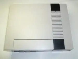
    • Drehe die Konsole herum und ziehe das obere Gehäuseteil vom Rest des Gerätes weg.

    the outside screws are a little deep, plan ahead :)

    Joseph McCord -

    Why use a slotted driver? The screws are phillips. Both #1 and #2 work for me.

    kmcrawford111 -

  2. WlRGREqDfRX5XcTU
    WlRGREqDfRX5XcTU
    IwactFKPXGkwbdmR
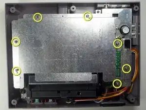
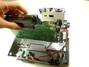
    • Entferne sieben 13,25 mm Kreuzschlitzschrauben #2 von der Metallabdeckung.

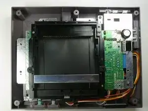
    • Ziehe die Metallabdeckung mit den Händen hoch und vom Rest des Gerätes weg.

  3. U3hHS514sOOJGH4O
    U3hHS514sOOJGH4O
    LMEuSKjdCqqnWLcu
    1EOlwLWfUKBQLetP
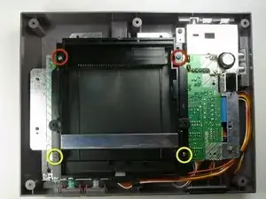
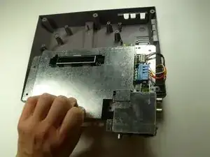
    • Entferne die beiden silberfarbenen 17,25 mm Kreuzschlitzschrauben #2 vom Einschub .

    • Entferne die beiden bronzefarbenen 13,25 mm Kreuzschlitzschrauben #2 vom Cartridge Einschub .

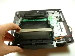
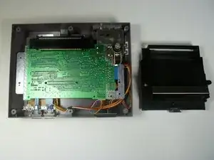
    • Schiebe den Cartridge Einschub zu dir , weg vom 72 Pin Verbinder und weg von der Einheit der Hauptplatine.

    There may also be two short/yellow screws at the upper (back) right and left of the cartridge tray.

    Jay -

  4. bR5tFq2ubQKbsQdy
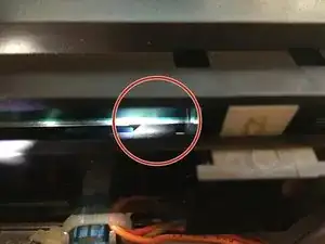
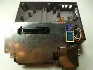
    • Unter dem Einschub ist eine Lasche/Lippe, im Bild markiert.

    • Achte darauf, dass diese Lasche unter der Hauptplatine passend zur Richtung mit dem Oberteil des Einschubs verläuft. Wenn das nicht stimmt wird sich der Einschub verbiegen und zu stark beanspruchen.

    This is so unclear! I have no idea what tab this step is referring to.

    trevorsklar -

    So, it’s a year later, and I have a lot more experience with this system now. The front of the cartridge tray needs to hook under the edge of the board.

    It’s much easier to get the tray on and off if you just make sure the board is unscrewed from the case. Then pick the board up a little and the tray should be much easier to slide on and off.

    trevorsklar -

    Me too... No idea whatsoever

    zac -

    its when your replacing the cartridge tray, if u do it wrong the tray will feel like it's bowing up in the middle, like when u put in the screws u have to press the tray down to get the screw holes to line up / be flush, if u get the lip underneath to catch correctly there will be no issue/bow u wan't have to press down on it, or make the screws pull the tray to the motherboard, instead the tray will be flush with no pressure applied, i had no idea what he meant either until i was reversing the steps.

    Joseph McCord -

    also not all NES are the same underneath, my tab was much less noticeable and i had one less screw to get the shield off then he showed. and 2 less screws to remove the cartridge tray.

    Joseph McCord -

    This seemed very unclear to me at first, until I tried to replace the cart tray. I apparently didn’t get the little lip under the mobo on my first attempt, and I noticed there was a pretty decent chunk of space between the front brass screw holes and their corresponding holes on the mobo. I reseated it, and the second time I heard a little click (apparently the lip going under the mobo). This time the bottom/brass screw holes were virtually FLUSH with the mobo holes. If you see a chunk of space between the cart tray and the mobo near the brass screw holes you didn’t get the lip under the mobo.

    Gary -

    I’ve added a new, better picture with additional clarification. Hope this helps.

    Steve -

  5. rohAFokIaTayMsCU
    rohAFokIaTayMsCU
    RkNYgOSWMtCgeWoj
    KZRgKExjUxhTZ6qQ
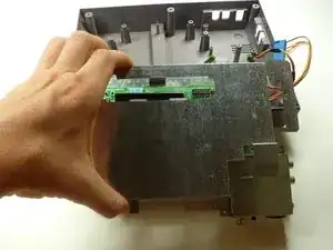
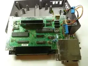
    • Entferne die drei 13,25 mm Kreuzschlitzschrauben #2 welche die Hauptplatine am Gehäuse festhalten.

    • Hebe die ganze Einheit der Hauptplatine gerade mit den Händen hoch und weg vom Gehäuse.

    • Drehe die Einheit herum, so dass die Metallabdeckung zu dir zeigt.

  6. 2duJSColf1CMSFsi
    • Löse das Kabelwerk von der Einheit der Hauptplatine:

    • Spieler 1

    • Spieler 2

    • Stromversorgung

    • Merke dir gut, welcher Anschluss Spieler 1 zu nehmen welcher Spieler 2 ist. Du kannst die Kabel markieren.

  7. Ae3sOlNCyfBEvBCA
    Ae3sOlNCyfBEvBCA
    mNetqQsCMM1VETiq
    XBEqCAQjfKieqs4F
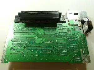
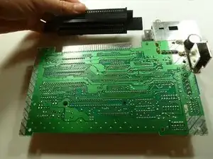
    • Löse das Abschirmblech von der Einheit der Hauptplatine.

    • Drehe die Einheit der Hauptplatine um, so dass der 72 Pin Anschluss oben liegt.

    would have been really nice to show a Step 8 in pulling off the 72-PIN connector has i had to just guess that it would just pull off. it took a little force and at first i thought it was attached via something i was missing, Also anyone who wants to know when removing player 1/2 and the power and reset "big blue tab" don't pull on the wires but try and get your fingernail/jimmy on either side and nudge it going back and forth until you get some release a little, then go to other side and so same until you can get a better grip and just pull it out

    Joseph McCord -

Abschluss

Um dein Gerät wieder zusammenzusetzen folge den Schritten in umgekehrter Reihenfolge.
nicholasweiser

Mitglied seit: 23/09/10

2586 Reputation

11 Kommentare

Because it wasn't terribly clear, the pin connector pulls off from the motherboard. Just pull straight away from the board to clear the connector. It takes some force to get it off.

Dylan Peterson -

And, no wires need to be disconnected either.

Very easy repair.

justinlamoureux -

"How to replace your 72 pin connector"

Leaves out the steps that show how to remove the 72 pin connector.

Priceless

punch0073735963 -

Um are we missing the last steps on how to actually remove the 72pin connector???

Connor Gray -

I replaced mine, and I'm still getting a solid white screen. Any ideas what else it might be?

Brandon Dixon -

The 10NES Chip. Mr. Glitch's Retro Reviews: HOWTO: Fix the NES Red Light Of Death (mrglitchsreviews.blogspot.com) See this guide to learn how to disable it.

Tristan Haugh -

I replaced my 72 pin connector and now it seems the games wont eject all the way up, it stops at like a midway point. And taking the cartridge in and out is super tough! Any ideas guys?

Matt Smith -

To remove the 72 pin connector once unscrewed just wiggle it out. Replacement connectors are very tight to insert and pull out games (this is normal).

Taylor hoskins -

Don’t waste your money replacing the 72 pin connector. Refurbish it without removing it from the mother board. Stop after step 2. Use a dental pic to bend the top 36 pins. It’s tedious……but free. Be careful not to over-bend them, you can fix it but it’s a pain. Take some fine grain sandpaper and fold a piece over the blade of a putty knife and duct tape it on. Insert the sandpaper clad putty knife into the 72 pin connector (straight in, straight out, don’t slide left and right while it’s in there) Move one putty knife blade width left or right and repeat until you have cleaned all the pins. Use a game that has already had it’s connectors cleaned to test the machine before you put the rf shield and the cover back on. If you can’t get the game to play re-examine the straightness of the pins you bent and run the sandpaper putty knife through there again. After you get it to work, then put the rf shield and cover back on.

temporalwisard -

I would very strongly advise against using sandpaper inside any cartridge-based system as it can leave some sand residue in the connections, which would in term wear out the contacts on the games faster.

Tsaku -

Also had problem with no picture on my Nintendo, replaced the reader, but still the same.

wallgrenanders6 -