Einleitung
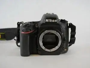
This guide will help you to get to the internal components of the Nikon D610 camera.


-
-
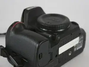
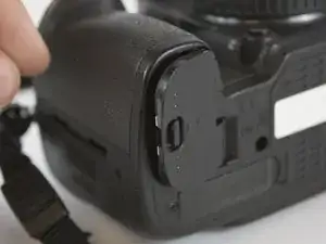
Set the camera so that it is sitting on its side.
-
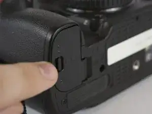
Open the battery compartment door by sliding the release button towards the lens.
-
This will cause the door to "pop" open slightly
-
-
-
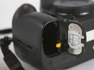
Now lift open the battery compartment door.
-
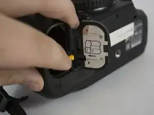
Push the yellow tab lock towards the center to release the battery.
-
Pull straight out, slowly on the battery.
-
-
-
After removal of the battery. Pull the battery compartment door away from the lens.
-
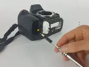
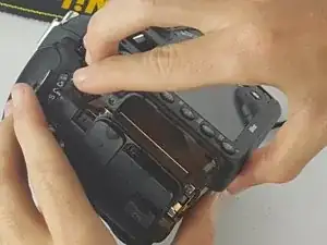
There are eleven Philips head screws that hold the bottom cover on, including a few inside the battery compartment.
-
Remove all the screws and the bottom face should pop off easily.
-
-
-
Then next step is removing the seven Philips #00 screws that hold the rear face plate on.
-
There are screws hidden in three separate spots.
-
One is under the rubber doors on the left side of the camera. the next one at the eye hole.
-
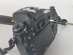
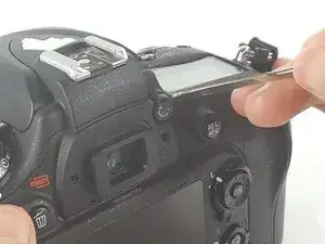
The final one involves taking off the small dial that is about half an inch to the right of the eye hole.
-
Removing this dial involves putting a spungder tool behind it and applying a gradual amount of pressure.
-
-
-
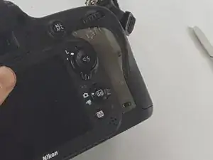
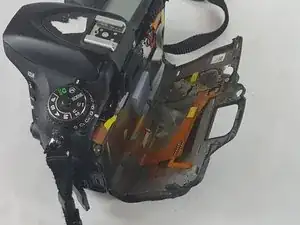
The rear face plate will include the LCD display it separates from the body of the camera with a small tug.
-
Once there is enough space it will be possible to gently pull the ribbon cable out of their ports.
-
-
-
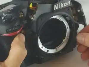
The next piece to come off is the front plate and the red grip.
-
The front plate is held on by 2 Philips #00 screws on the front and two more beneath the flash bulb.
-
Remove the two Phillips #00 screws holding on the grip and it slides off easily.
-
-
-
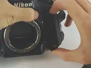
It is now possible to remove the last three Philips #00 screws that are hidden under the memory card slot door.
-
The screws come out and the cover comes straight off.
-
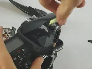
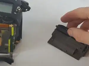
The last cover plate is the top. The top is held on by two screws located just beneath the rim of the cover.
-
To reassemble your device, follow these instructions in reverse order.

2 Kommentare
useful thank you
Loic -
Very useful guide, thank you. I have some damage to my rear casing and have a replacement which I would like to install. From your photos it looks as though there is a lot of dismantling to do to achieve this. Is this very difficult for an amateur to do? I do have a replacement casing.