Einleitung

  1. lSX3YKkAqXS3UGcj
    lSX3YKkAqXS3UGcj
    3EBkhUnyhXkaswHF
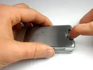
    • Turn the phone off.

    • Remove the back cover by sliding the tab away from the phone using one finger.

  2. p5QARnCM5cYMDNh3
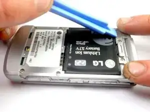
    • Lift one side of the battery using a plastic opening tool or your fingers.

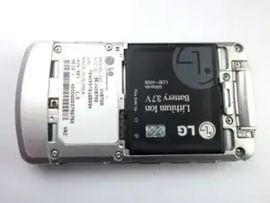
    • Carefully remove the battery and set it aside.

  3. ASQlssJqLRTGC44l
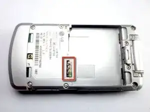
    • When installing the battery, make sure to align the metal pins with those of the phone.

  4. jBk4BYyNLLC5Vvh3
    jBk4BYyNLLC5Vvh3
    sLFdQHIOGRIceaOI
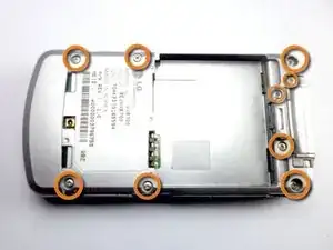
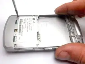
    • Use a Phillips #0 Screwdriver to remove the nine 4 mm screws from the back cover.

  5. YbeCB6l1r4yoVuvQ
    YbeCB6l1r4yoVuvQ
    GUALQ6WQhZlAMMwp
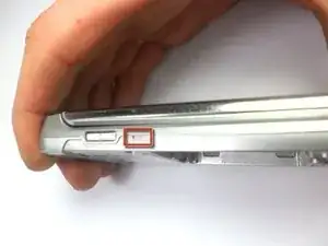
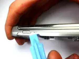
    • Insert the tip of the plastic opening tool into the small notch on the side of the case.

    • Slide the opening tool along the seam and around the edge of the phone to separate the case.

  6. WxNENfTvmXEHWg3r
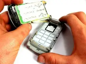
    • Separate the two halves of the phone.

    • On the left is the back of the phone holding the logic board and key pad.

    • On the right is the plastic casing.

  7. 3Uf2KVIQBtTEVcne
    3Uf2KVIQBtTEVcne
    sQ2SuRGhpcZpgJyR
    ywStMnUnGoZEWGse
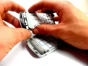
    • Holding the phone casing with one hand, and the key pad assembly with the other, separate the phone case from the keypad/logic board.

  8. wkusIhx3H2AtGKJb
    wkusIhx3H2AtGKJb
    GMBHGrfFVTLuDf1r
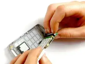
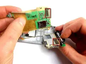
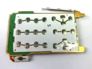
    • Remove the key pad from the logic board by pulling the two boards apart, separating this connection.

  9. OvQslfGniG6jFlRe
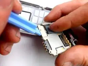
    • First, pull back the tape covering the connection between the motherboard and the ribbon cable.

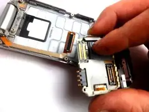
    • Separate the connection, using the plastic opening tool.

  10. 2nxlAN6RNyNNWLnd
    2nxlAN6RNyNNWLnd
    6uhxwr1qStAQDtQQ
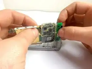
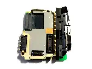
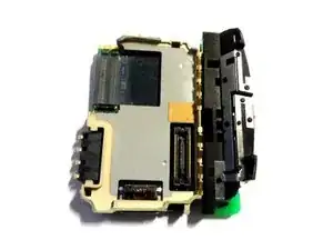
    • After the connection is removed, the motherboard is successfully removed.

Abschluss

To reassemble your device, follow these instructions in reverse order.

Stanley Thomas

Mitglied seit: 20/01/12

41 Reputation

0 Kommentare