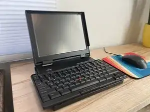
Einleitung
Werkzeuge


-
-
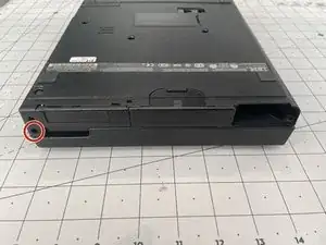
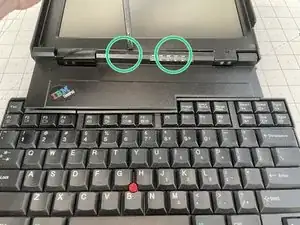
Remove the 5mm screw with a T6 Torx bit from the right side by the screen hinge.
-
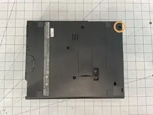
Rotate the laptop so the screen hinge is at the rear. Remove the 16mm screw using a T6 Torx bit.
-
-
-
Open the screen so its a bit past vertical and rotate the back of the laptop toward you.
-
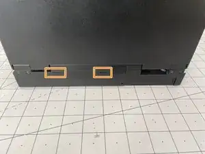
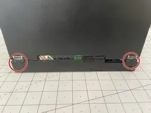
Using a plastic spudger, push the two plastic tabs while lifting up gently on the top plate.
-
Lay the screen completely flat and use a plastic spudger to push the back of the top plate up and towards you.
-
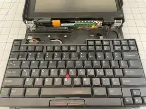
You should now able to lift the top plate up and out, exposing the LCD converter board and keyboard track.
-
-
-
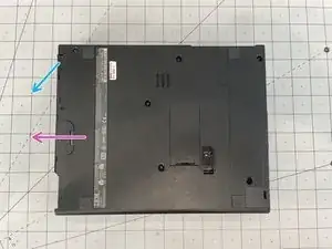
Remove the PCMCIA cover by pushing out on the top edge and rotating downward to release the hard drive.
-
Remove the Hard disk drive by sliding the unlock button and pushing it out.
-
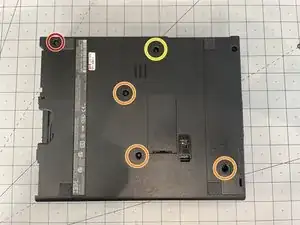
Flip the laptop over so the screen hinge is facing away from you. Remove the 8mm screw at the top left with a T6 Torx bit.
-
Remove the three (3) 6mm screws from the middle and bottom right with a T6 Torx bit.
-
Remove the 10mm screw from the top center with a T6 Torx bit.
-
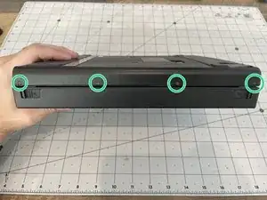
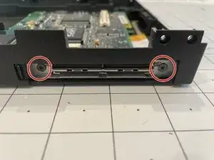
Remove the four (4) 2mm screws freom the front of the lowe case using a T1 Torx bit.
-
-
-
Flip the laptop over so that the display hinge is facing you and open the display to a 90 degree angle from the chasis.
-
Remove the four (4) 7.5mm screws from the back using a T6 Torx bit. At this point the screen will come free.
-
Carefully pull up to remove it from its posts and rest backwards, exposing the next screw.
-
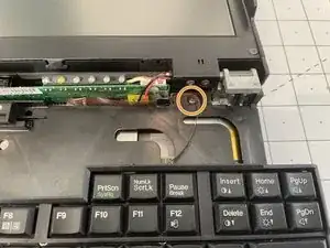
Remove the 5mm screw from the top right of the chasis using a T6 Torx bit.
-
-
-
To remove the keyboard, push the assembly back towards the display, releasing it from the front clips and tilt it up towards the display.
-
Using a plastic Spudger tool, remove the ribbon cables from connectors and set it aside.
-
Lift off the keyboard and set aside.
-
-
-
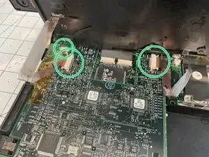
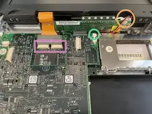
Disconnect microphone cable from the daughter board using a plastic spudger tool.
-
Disconnect the power cable to the display inverter board.
-
Disconnect display ribbon cables from the daughter board using a plastic spudger tool.
-
Pull the display up and away and set aside.
-
-
-
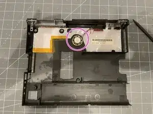
Disconnect the speaker cable.
-
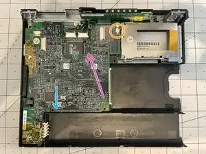
Use a plastic spuger to press down on the system board where indicated during the next step to safely disconnect the daughter board from the main system board.
-
To disconnect daughter board from connector. Tilt up from right side and remove up and to the left.
-
-
-
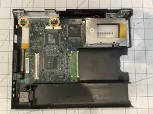
Remove two (2) 5mm scews close to the connector using a T6 Torx bit.
-
Turn the case around so the back is facing you and remove two (2) 6mm screws from the back holding the connector to the metal stiffener.
-
Lift off main board.
-
-
-
Using a plastic spudger or a hobby knife, carefully loosen the glue between the speaker and the case.
-
Remove the speaker and set aside.
-
-
-
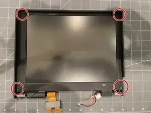
Remove the four (4) 8mm screws from the inside frame using a T6 Torx bit.
-
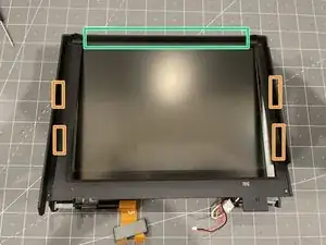
Lift the inner housing from the bottom. There are 4 clips to dislodge on the edge of the screen.
-
The top may be glued to the outer frame, so after you release the clips on the side, you'll want to tilt the inner frame away from you.
-
Lift inner housing out and set aside.
-
Tilt the display so you can see the under side. Remove the four (4) 7.5mm screws from the bottom using a T6 Torx bit to release the hinges.
-
Life the hinges out from the top and set aside, along with the metal keyboard guide attached to the left.
-
You can now tilt out and remove the display from the housing.
-
To reassemble your device, follow these instructions in reverse order.