Einleitung
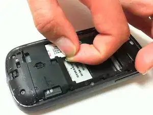
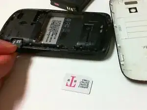
This guide demonstrates the procedure for replacing a faulty camera in the HTC myTouch 3G.


-
-
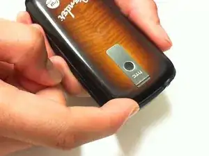
Press both thumbs on each side of the upper corners, and apply pressure in a downward motion.
-
While applying pressure, slide the back cover down.
-
-
-
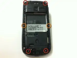
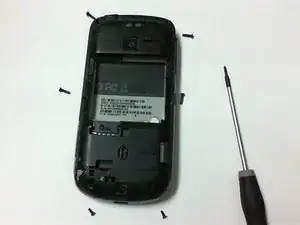
Remove the four 6 mm T5 Torx screws from the four corners on the back of the phone.
-
Remove the two 4 mm T5 Torx screws from the middle of the back of the phone.
-
-
-
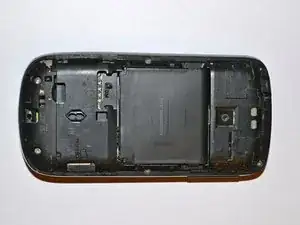
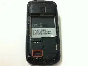
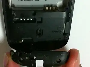
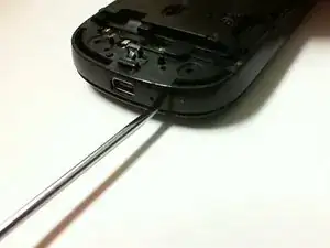
Insert a spudger into the slit between the frame and cover, and push downward to dislodge the back plate from the phone.
-
Use the spudger to go around the edges of the phone to further dislodge the back plate.
-
-
-
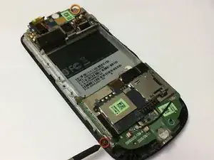
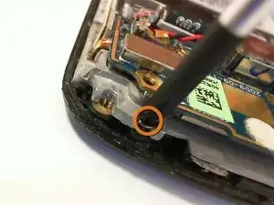
Remove the 3 mm Phillips screw located on the side of the bottom left-hand corner of the phone.
-
Remove the 3 mm Phillips screw located on the top right-hand corner of the phone.
-
-
-
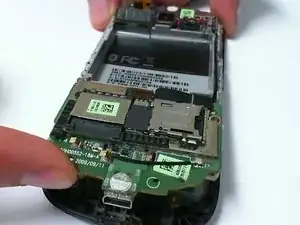
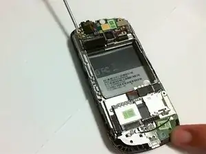
Place a finger between the circuit board and front cover, and lift up gently.
-
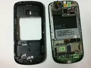
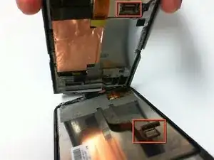
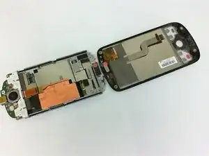
Separate the circuit board from the front cover and screen to detach the ribbon cable holding them together.
-
Finish separating the circuit board from the front panel.
-
-
-
Turn the piece housing the circuit boards over to the side with the mounted camera.
-
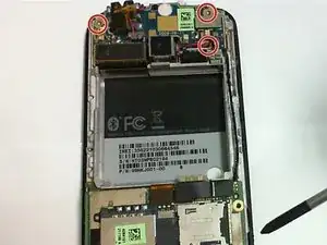
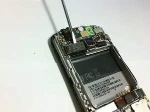
Remove the three 3-mm Phillips head screws located on the top circuit board.
-
-
-
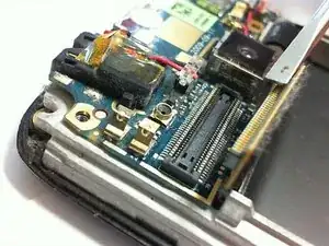
Locate the ribbon cable on the top circuit board.
-
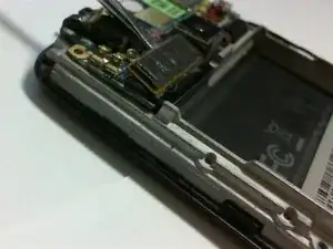
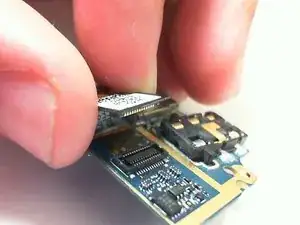
Disconnect the ribbon cable by using a precision screwdriver to flip open the ribbon cable.
-
-
-
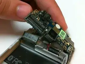
Slowly lift the circuit board from the left.
-
Continue to flip the circuit board all the way over to the right.
-
-
-
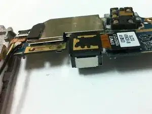
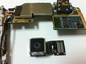
The other side of the camera and circuit board should be exposed.
-
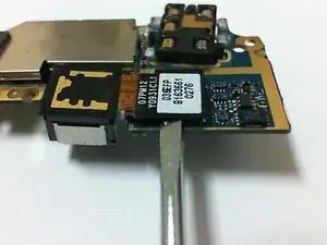
Disconnect the ribbon cable with a precision screwdriver.
-
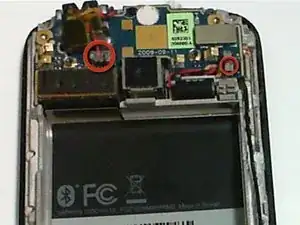
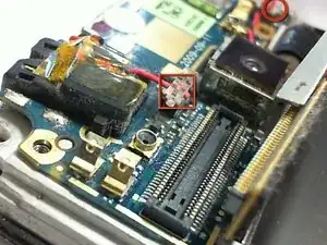
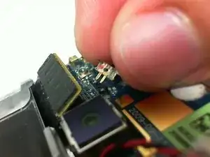
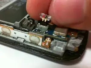
Remove the faulty camera and replace with a new one.
-
To reassemble your device, follow these instructions in reverse order.
