Einleitung
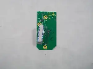
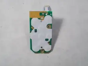
During this guild you will learn how to get to the inner components of the camera and how to remove the button circuit board.
Werkzeuge


-
-
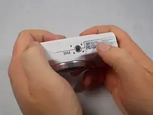
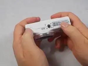
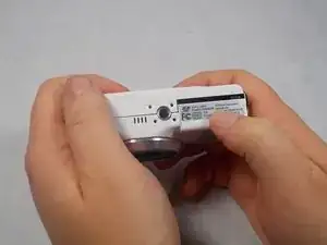
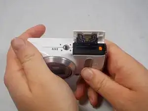
Hold the camera upside down with your right thumb on the battery chamber cover.
-
The lens should be be facing your body.
-
-
-
While holding the camera, pull the battery chamber cover towards your body with your right thumb.
-
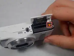
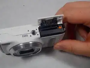
Once you pull the cover all the way out release it, this will reveal the battery.
-
-
-
There is an orange battery latch that holds the battery down in place, with your finger push that latch away from you and this will release the battery.
-
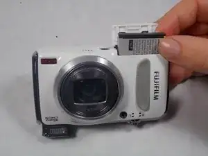
Once the battery is released grab the battery with your right thumb and pointer finger and remove it from the battery chamber, try putting it on a charger, if that is not the problem then a replacement battery is necessary.
-
-
-
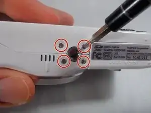
Remove four 2.5mm Phillips #1 screws on the bottom of the camera near where the camera mount attaches.
-
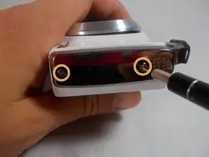
Remove two 5.1mm Phillips #1 screws on the left side of the camera relative to the LCD screen.
-
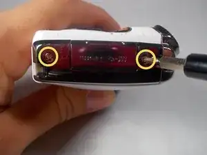
Remove two 5.1mm Phillips #1 screws on the right side of the camera relative to the LCD screen nearest to the mode wheel.
-
-
-
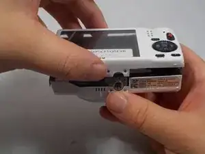
Place the camera lens face down with the LCD screen face up on a flat surface, or hold it. Carefully lift the camera’s back cover approximately 1 inch.
-
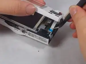
Carefully lift the ribbon clamp connector back using the tweezers and remove the blue ribbon.
-
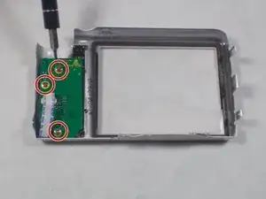
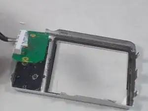
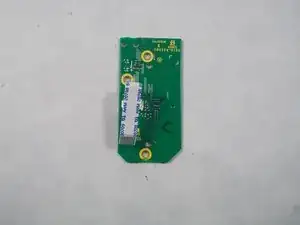
To reassemble your device, follow these instructions in reverse order.
