Einleitung
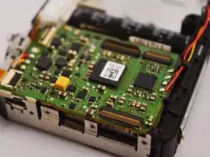
This guide will describe how to replace the mother board of Casio Exilim EX-Z80. Notice that before we can start to do this part, we need to remove the front&back cover, LCD screen and lens. This guide will involve some key points step by step to replace the mother board.


-
-
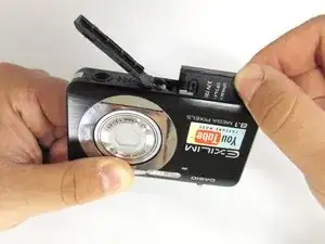
Locate the battery compartment at the bottom of the camera.
-
With your thumb, gently press down on the compartment door and slide to the left to open.
-
-
-
With your index finger, gently pull back gray release lever for the battery to pop out.
-
Gently pull the battery out of the slot.
-
-
-
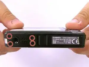
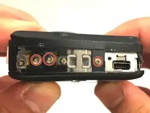
Locate the screws on the bottom of the camera.
-
With the #000 screw driver, remove the 4 3mm black screws.
-
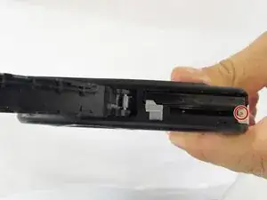
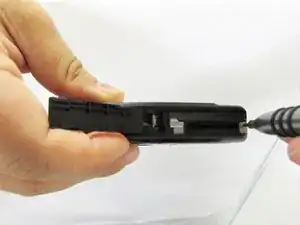
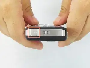
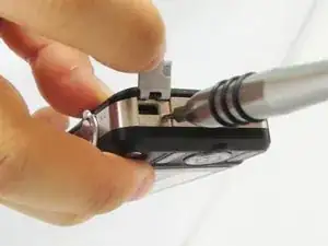
With your thumb or index finger, open the battery compartment and with the #000 screw driver remove the 2mm silver screw that is now exposed.
-
-
-
Locate the USB port of the camera.
-
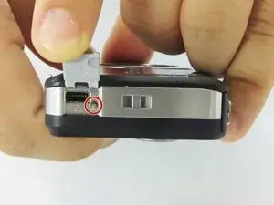
Open the usb port tab to expose a 2mm silver screw.
-
With the #000 screw driver, remove the 2mm silver screw.
-
-
-
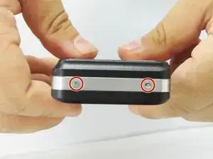
Locate the 2 exposed screws on the other side of the camera.
-
With the #000 screwdriver remove the two 2mm silver screws.
-
-
-
Carefully remove the silver strip from left side. Open the battery cover and remove the metal strip with fingers by sliding it to the left.
-
-
-
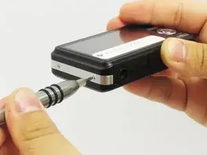
With the metal spudger, pry out the edge of the silver strip at the bottom right side of the camera.
-
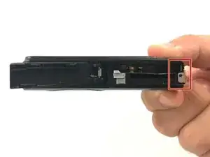
Carefully remove the remaining part of the metal strip.
-
-
-
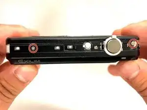
With the #000 screwdriver, remove the 2mm silver screw from the top corner of the camera near the shutter button.
-
With the #000 screwdriver, remove the second 2mm silver screw.
-
Do the same thing on the left side using #000 for the three 2mm screws.
-
-
-
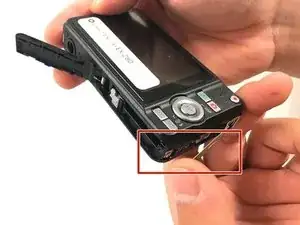
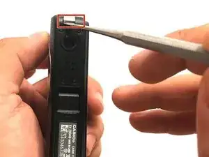
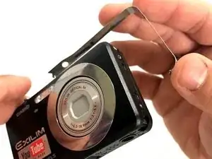
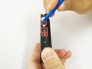
Using a small opening tool carefully release all lock tabs at the top and on the side of the camera from their locked position.
-
Using your hands, carefully separate the front and back panel from the camera.
-
-
-
Carefully flip the wide button cable up from the display cable.
-
Use the tip of a spudger to lift the brown retaining flap on the display cable ZIF connector.
-
Carefully pull the display cable from its connector.
-
-
-
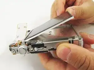
Pry up the LCD screen using a metal spudger. There are several little square holes for locking the LCD screen. Pry them up until the raised little tabs are out of the metal holes.
-
Do the same for all little holes around the four edges of the camera.
-
With all little tabs raised are pried out. The LCD screen should be pried up using metal spudger very easily. Insert the spudger into the gap of the metal case and pry up the LCD screen.
-
-
-
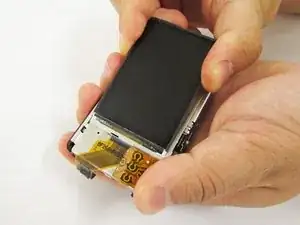
When the LCD screen is pried up, hold it with your hand and do not allow it fall back into the metal case.
-
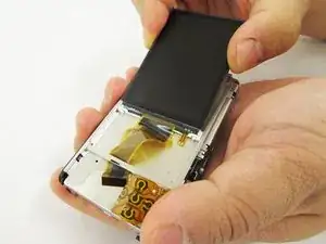
Hold the LCD screen in one hand and hold back the button cable with the other.
-
Pull on the LCD screen until the yellow display cable is completely out of of the metal case.
-
-
-
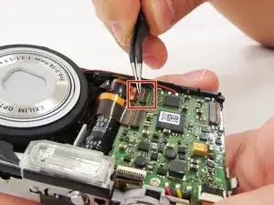
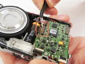
Lift the retaining flaps on the two ZIF connectors that secure the the lens ribbon cables to the motherboard.
-
Carefully pull the two ribbon cables from their sockets on the motherboard.
-
-
-
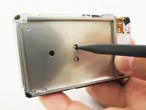
Turn the camera around and locate the holes on the metal panel.
-
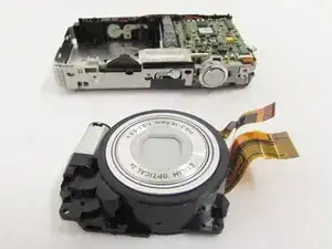
With a heavy duty spudger, gently poke through the holes, releasing the lens from the main portion of the camera.
-
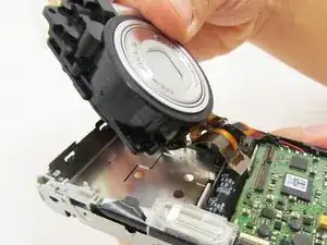
With your index finger and thumb gently pull the full lens out.
-
-
-
First turn the camera face up with the mother board facing you.
-
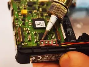
At the bottom of the motherboard, there are four nodes. With the soldering iron, desolder the metal nodes to release the wires from the board.
-
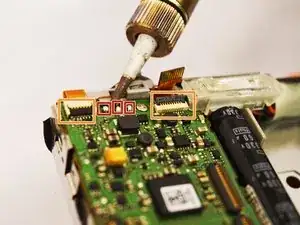
With the soldering iron, desolder the three remaining nodes at the top of the motherboard.
-
Lift the two black retaining flaps on the ZIF connectors at the top of the motherboard.
-
-
-
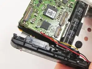
Gently pull the black plastic case from the bottom of the camera.
-
Pull out the little white plastic (the power button) on the top of the camera. It may be covered by a piece of black tape. Pulling the tape will allow for the power button to be released.
-
-
-
Insert a metal spudger into the edge of the camera shutter button and pry the button out.
-
Then remove the button with your hand
-
-
-
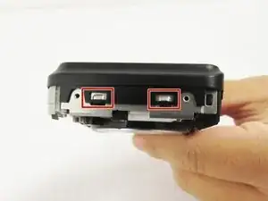
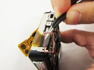
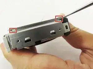
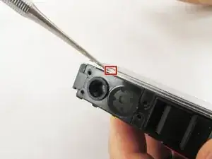
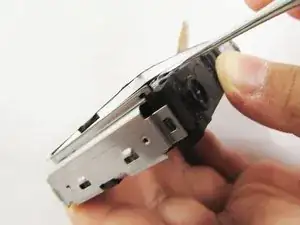
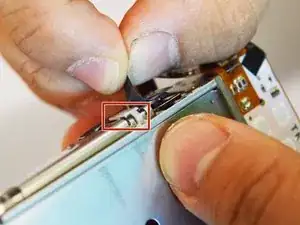
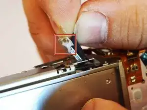
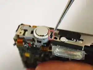
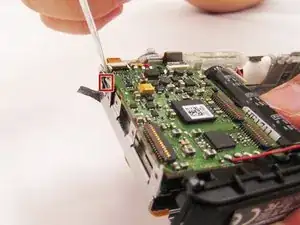
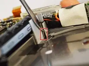
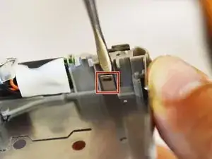
Use the metal spudger to pry the iron tabs in order to free the motherboard. There are three places to pry. Once you are done, the mother board should be able to move.
-
-
-
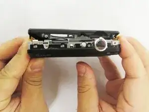
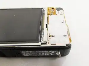
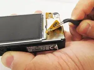
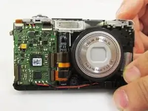
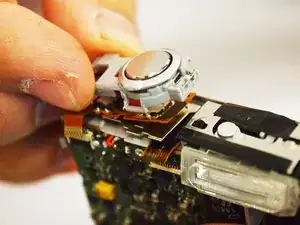
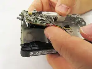
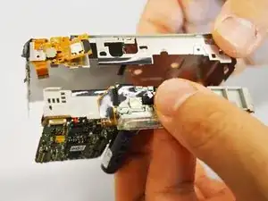
Gently move up the motherboard from the bottom of the camera. The motherboard can then be pulled out at the top of the camera.
-
Use gentle force to pry out the motherboard.
-
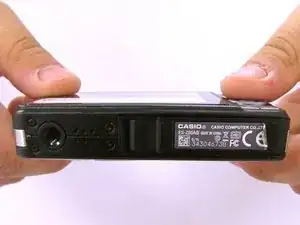
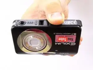
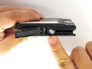
To reassemble your device, follow these instructions in reverse order.
