Einleitung
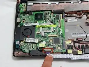
This guide is fairly long, but if you follow all the instructions closely and pay attention to the sensitive parts of the machine, it should be a mostly simple process. There are some fragile pieces exposed during this process: the touch pad ribbon, the LEDs at the top of the casing under the keyboard, the WiFi antenna, and the motherboard. With some base level of care these components should be fine, they're meant to be moved around. Take it slow, it's easier than it looks!
This guide goes through the process of removing both the fan and the WiFi antenna, so if you're looking to replace either this will help. It also accesses the hard drive and SD card module, so it may help if you're looking to replace your hard drive or ensure your SD card module is working.


-
-
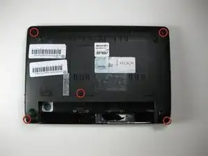
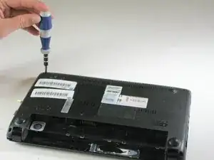
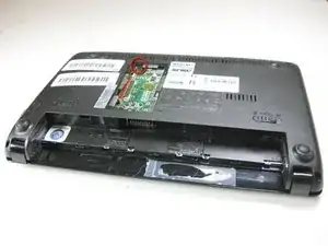
Remove (6.65 mm) screw next to RAM.
-
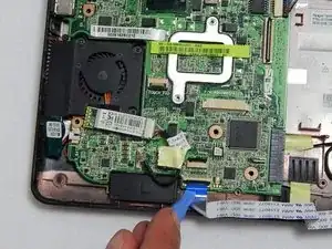
Identify and disconnect touch pad ribbon cable which can be seen through a window at the bottom edge of the metal part of the top casing (in these photos the connector shows blue).
-
-
-
Turn computer right side up, and open it.
-
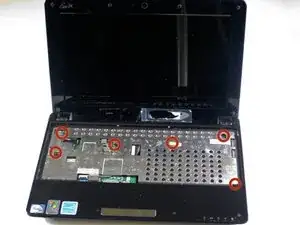
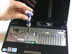
Remove 6 (5.5 mm) screws from inside covering.
-
Disconnect the touch pad ribbon cable.
-
-
-
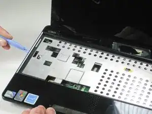
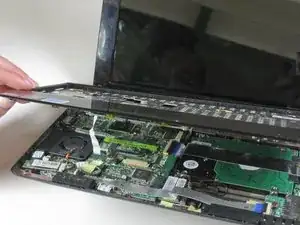
Detach each of the 5 plastic clips. Run a plastic opening tool along the underside of the top half. You will hear the 'clicks' of the clips coming undone.
-
After the clips are loose, disconnect the palmrest flatflex and remove it.
-
-
-
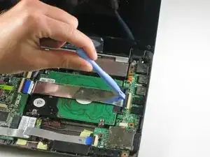
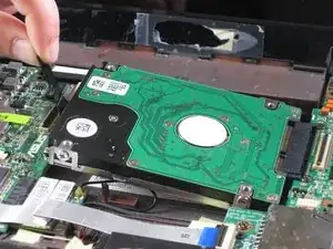
Remove the hard drive ribbon by lifting the black clips upward.
-
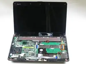
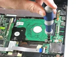
Remove (4.6 mm) screws that hold the hard drive in place.
-
-
-
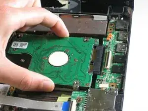
Gently pull the hard drive to the left by the black plastic ribbon. Slowly lift the hard drive up on the left and then out.
-
-
-
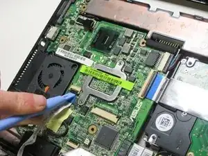
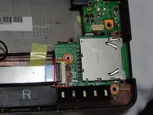
Lift the black clips using the plastic opening tool to detach the ribbon that connects the SD card module.
-
-
-
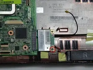
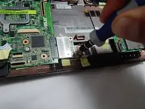
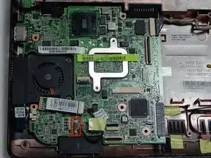
Remove this screw, which holds the wifi component in place, using the Phillips head screwdriver.
-
-
-
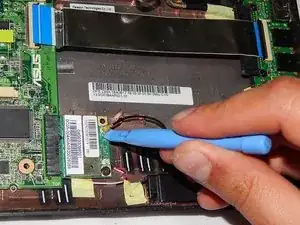
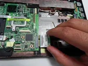
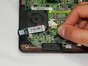
Pull the Wi-Fi component to the right, and then slightly upward and finally out to remove the Wi-Fi antenna.
-
-
-
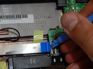
Detach the ribbon cable that connects the SD card module and the motherboard by lifting the black clips using the plastic opening tool.
-
-
-
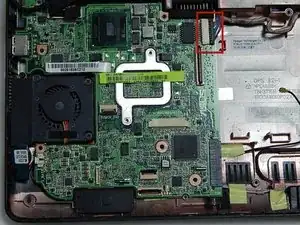
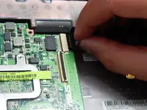
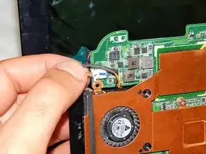
Detach the black structure connected to the input cables in the top right center of the motherboard by pulling them to the right, away from the fan.
-
-
-
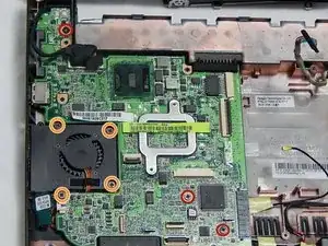
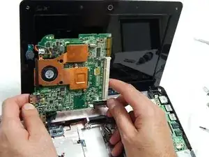
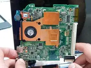
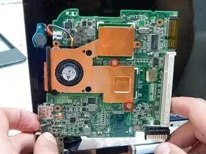
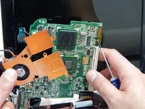
Remove the three 5.5 mm screws holding the motherboard to the motherboard plastic frame.
-
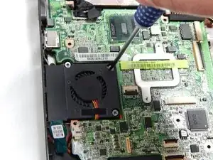
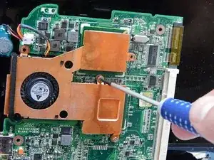
Remove the four 5.5 mm screws surrounding the fan.
-
To reassemble your device, follow these instructions in reverse order.