Einleitung

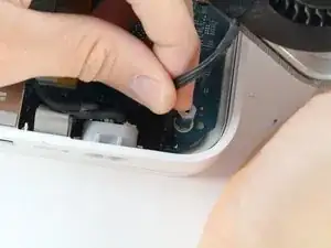
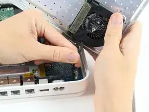
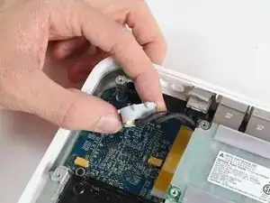
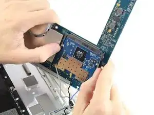
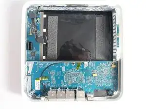
Das Logic Board ist das zentrale Nervensystem der Time Capsule . Ohne Logic Board würde die Time Capsule nicht funktionieren. Die Ethernet-Anschlüsse sind auf dem Logic Board befestigt. Sollte einer davon beschädigt sein, muss das Logic Board ausgetauscht werden. Benutze diese Anleitung, um die beschädigte Komponente einfach zu tauschen.

  1. tTKxZScNSUUeylGJ
    tTKxZScNSUUeylGJ
    xH2qZgTP3aBrgdNN
    jV1pBpi5FVSnvyPC
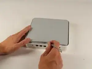
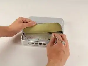
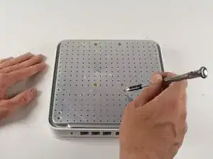
    • Drehe das Gerät um, um an die Gummiabdeckung der Rückplatte zu gelangen. Schiebe vorsichtig die stumpfe Spitze des Metall-Spudgers in den Spalt zwischen Aluminium-Rückplatte und Gummiabdeckung, um die beiden Teile voneinander zu lösen.

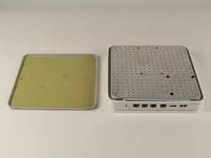
    • Das Gummi zu entfernen kann einige Minuten dauern. Sobald du das Gummi komplett greifen kannst, ist es einfacher mit der Hand zu entfernen.

    • Kümmere dich nicht darum, neuen Kleber auf das Gummi aufzutragen, der noch vorhandene Kleber darauf reicht völlig aus, um die Gummiabdeckung wieder auf das Aluminium zu kleben.

    The epoxy cementing the rubber pad to the aluminum base is a lot stronger than the rubber itself. The rubber is likely to tear as you remove it; I had to use a putty knife to clear the screws. It's worth hanging onto the branding near the Ethernet ports, for future identification (model number, serial number, Ethernet ID, AirPort ID); you can fashion a replacement pad out of neoprene rubber.

    adlerpe -

    Mine completely ripped I have no back cover now its in multiple pieces…. mine was giving off way to much heat and hard drive errors so I decided to replace hard drive and fan wish me luck BUT if yours is overheating do not expect to get back off without ripping the rubber to

    William -

    Using a fan to heat the plate up was helpful

    Michael Zimmermann -

    I wish I read Michael Zimmermann’s suggestion before I tore the first half into about 15 pieces! On the second half I used a hair dryer to heat the rubber. With enough heat and a very slow steady pull on the rubber it came of as a single piece :-)

    mfred2 -

    Do I need to put back on the rubber? will it overheat if I don’t?

    Strider -

    It is almost impossible to keep the bottom rubber covering intact in one piece. The rubber is covering the whole base section and it won’t be a problem without it I guess. This is not an epoxy because it is still gummy and sticky. This is like the adhesive used on the double side tapes. Goo Gone worked well to remove those residues.

    Kenn Sakurai -

    The rubber cap like bottom can be replaced with easy to cut in shape cork sheet will do. Just rip off the thin strip where the serial number for the ID and other info that might be needed later. Have it glued or put on a clear tape and put it on the side of the white plastic sidewall will do.

    Kenn Sakurai -

    With age, the rubber becomes brittle. It is best to heat it up with a hair dryer before trying to gently peel it off.

    SirDeck -

  2. k1gaTVXRCTGlVPMO
    k1gaTVXRCTGlVPMO
    GxUJka5DUcosaBKH
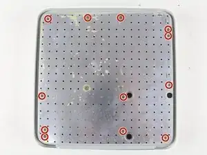
    • Entferne die zehn 3 mm Schrauben mit einem #00 PH Kreuzschlitzschraubendreher.

    • Die Schrauben, die mit Klebefolie bedeckt sind, brauchen nicht entfernt zu werden.

    The two screws in the top center of this picture should not be removed at this time. They are locating pins on the hard drive.

    neil.davenport -

    Correct - the four screws top centre with glue over then do not need to come out. They are only locating posts for the HDD.

    Tony Meredith - 2018-06-26

    Tony Meredith -

    There are twelve screws marked in that picture. AFAIK only ten need removing. The two in the middle of the top edge don’t need removing

    Shimbo -

    CONFIRMED. Thank you very much for the screws which should not be removed. You guys are right.

    Kenn Sakurai -

  3. YbXTvkOnaNUVHNQ6
    YbXTvkOnaNUVHNQ6
    dwpZPX4ItVpdjSR5
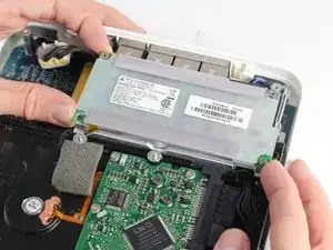
    • Der Lüfter ist auf der Rückplatte befestigt und mit dem Logic Board verbunden. Hier muss ein kleines Kabel entfernt werden, um die Rückplatte komplett zu entfernen.

    • Ziehe das Kabel vorsichtig in Richtung Logic Board, um den Stecker zu lösen.

    Be careful you do not rip the locating connector off the circuit board like I did.

    David “Milky” Millward -

    Do not disconnect the fan for a simple change of hard drive. With age, the connector becomes very fragile.

    SirDeck -

  4. EEsxoGVlCmLd3NrP
    EEsxoGVlCmLd3NrP
    EammFPZi4aL4Xi3L
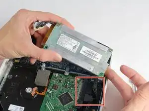
    • Entferne den externen Stecker aus seinem Gehäuse, indem du ihn zuerst anhebst und dann herausziehst.

    • Nimm das interne Netzteil aus dem Gerät heraus.

    • Du musst vermutlich leicht daran hin und her wackeln, um das Netzteil nach oben hin herauszubekommen, aber es lässt sich problemlos nach oben wegheben, da es durch nichts anderes befestigt ist.

  5. SOT43PgenmKYCCi1
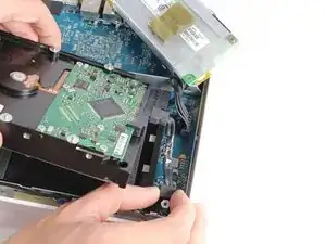
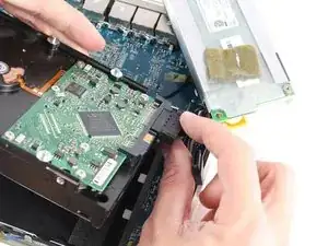
    • Entferne den SATA Stecker von der Festplatte. Das Kabel hat keinen Verschlussmechanismus und lässt sich einfach herausziehen.

  6. cxUDJVtreP5y4RnW
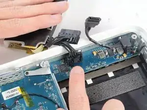
    • Entferne das Hauptstromkabel vom Logic Board.

    • Sei vorsichtig wenn du die Lasche auf dem Logic Board Stecker hineindrückst, um den Kabelverschluss zu lösen.

    note: The tab is connected to the connector of the cable not the logic board

    yogy11 -

    Hi there. This is probably a few years late. But where does one find a replacement PSU for this model Time Capsule?

    Matt -

    very easy to find a replacement one on ALIEXPRESS. I bought one, it was not new but a refurbished but it works.

    https://fr.aliexpress.com/item/400119317...

    very to change it

    Luxembourg -

  7. NGNtKGOj353i2Aym
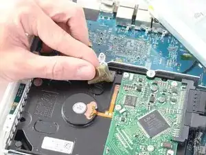
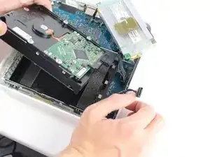
    • Ziehe den mit Klebstoff versehenen Schaumstoff von der Oberseite des Laufwerks ab.

    • Hebe das Laufwerk gerade nach oben aus dem Gerät heraus.

    Probably worth noting that the adhesive backed foam is covering what appears to be a temperature sensor which is stuck to the drive. That needs to be removed and installed on the new drive too. In addition there are pins and rubber boots (which may still be attached to the metal cover removed in step 2) on the drive which need to be transferred to the new drive. I couldn't unscrew them from my drive and had to use pliers to loosen them.

    neil.davenport -

    One should also remove the 4 distance pieces/spacers (2 aluminum screws [P1] on each side of the hard drive).

    Lars Clasen -

    No need to remove the distance spacers, the drive will come out anyway.

    Tony Meredith -

  8. 4cBBPocAreZNlYhg
    4cBBPocAreZNlYhg
    S2tSLUaYCIJRnoSc
    ZPGWLn1RiGN1c1PA
    • Entferne den SATA Stecker sowie den Stromstecker vom Ende der Festplatte, indem du die Kabel einfach gerade von den Anschlusspunkten abziehst.

    https://d3nevzfk7ii3be.cloudfront.net/ig...

    In the photo showing the bottom of the capsule and the 12 circled screws: only 10 need to be removed (as the instructions say). In this step, do not remove the 2 screws at the top center.

    After the hard drive is removed, unscrew the 4 standoffs from the old drive and transfer them to the new hard drive. Be sure to account for all 4 grey rubber "o-rings" that go on these standoffs.

    Reassemble.

    Format the new drive using Airport Utility.

    davec2468 -

    Once the hard drive is removed, can it be installed in an aftermarket enclosure and using as an external drive.

    Oldirish1948

    Fred McFaddin -

    That is my question too. I have one of these and I want to put the hard drive in my iMac. Will that work?

    Alec -

  9. 2gSUhMY5UqKuhvVa
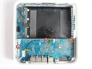
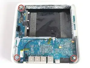
    • Entferne die drei 4 mm Schrauben von der Unterseite des Boards mit einem #0 Kreuzschlitzschraubendreher.

    • Die mittlere Schraube geht durch einen kleinen Befestigungsbolzen aus Aluminium. Achte darauf, dass du ihn nicht verlierst, du brauchst ihn beim Zusammenbau.

  10. hEWS1mZLYUHeeoVI
    hEWS1mZLYUHeeoVI
    e6dTwDvnrvvQ5auD
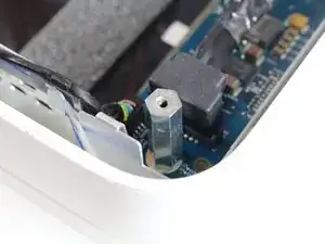
    • Entferne die drei sechskantigen Befestigungsbolzen, indem du sie gegen den Uhrzeigersinn herausdrehst.

    • Manche der Befestigungsbolzen müssen möglicherweise vorher mit einem Schraubenschlüssel oder einer kleinen Zange gelöst werden, bevor sie per Hand entfernt werden können.

  11. PYOVMDQhSE2ptLV2
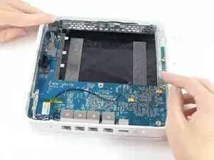
    • Drücke die beiden Aluminiumlaschen hinein, um das Board anzuheben und es unter den Laschen herauszuholen.

    • Das Board ist weiterhin durch Stecker am Gehäuse verbunden. Entferne das Board in diesem Schritt noch NICHT! Löse es lediglich unter den Laschen heraus.

  12. GtWyuVIqpTJBtEjK
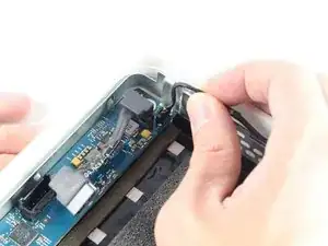
    • Entferne das LED Kabel aus der oberen linken Ecke des Logic Board, indem du das Kabel gerade heraus und vom Board wegziehst.

  13. ZZvTpRY3hZyCDqD1
    • Ziehe die beiden angezeigten Laschen von der RAM Karte weg, und ziehe die Karte heraus.

    • Das kann mit nur einer Person etwas schwierig werden. Frage einen Freund, um ein zweites Paar Hände zu haben.

Abschluss

Um dein Gerät wieder zusammenzusetzen, befolge die Anleitung in umgekehrter Reihenfolge.

Patrick Butler

Mitglied seit: 06/10/16

1047 Reputation

2 Kommentare

Between step 12 and 13 there is no detail on how to remove the board! I did the procedure until step #12 but board is firmly attached to the case! even after pullling the metal tabs it’s still glued to the base, please help

Juan Fonseca -

The board seems stuck because of sticky thermal pads between the chips and the housing. Assuming all screws are removed and cables disconnected, you should be able to pull up the board by just applying force. Hope this helps.

Steffen Moldekleiv -